X-Arcade™ BYO Kit Advanced Installation Diagram


NOTE: Mode B is the Save/Load button for programming.
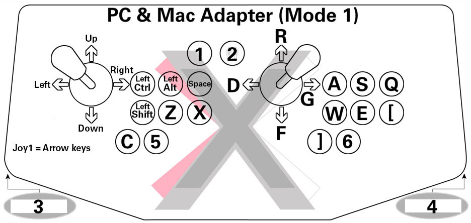
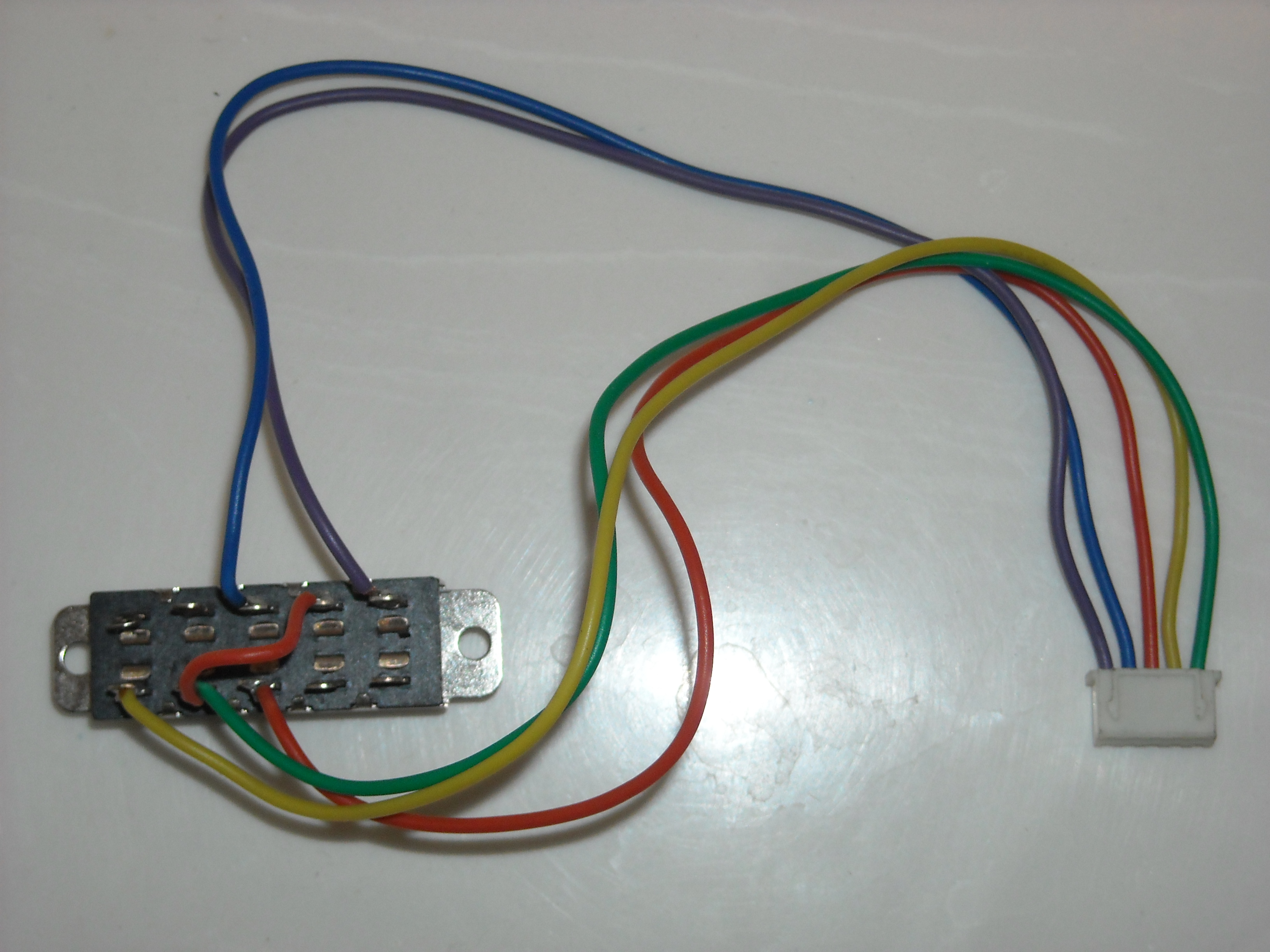
Wiring pinout for Mode switch and PCB-Cable.

Old Serial-PS/2 Cable Pinout Here
Trackball wiring:
The Trackball assembly may look complicated because it has many wires and connectors coming out of it, but there actually only 5 types of wires with several duplicates of each. Here are the functions for each wire color respectively :
- Black = All black wires are ground (use a ground with each wire below)
- White = Mouse Button 1 (mouse 0 in MAME) - On X-Arcade = Left Pinball button
- Brown = Mouse Button 2 (mouse button 1 in MAME) - On X-Arcade = Right Pinball button
- Orange = Mouse Button 3 (mouse button 2 in MAME) - On X-Arcade = Red-lit Exit button
- Blue = Horizontal Disabler (use for perfect straight shots in Golf or Bowling)
Terminal and Wire Sizes:
The X-Arcade brand microswitches and terminal connectors are .187". The wire is 20AWG.
PCB-Cable Clip:
Drill a 1/2" hole for the clip for wood enclosures.
Extending Wires:
If you need to extend the wires for your particular project, you will need to splice the wire (meaning cut it and add wire). The easiest way to do this is to purchase an extra wiring harness here, which will allow you to cut the wire with connectors already attached. You can alternatively buy some 20awg wire and simply add it to the wire you already have. You can connect 2 wires together by either using a) butt connectors, b) wire nuts, or c) solder and heat shrink tubing.
Here is a video showing these methods.